November 26th 2016
This is where things will get interesting. This is the main reason for this whole project. We got the motor out and the orders from Max BMW and Cycleworks have come in. I’ll try to document the process with as much detail as possible.
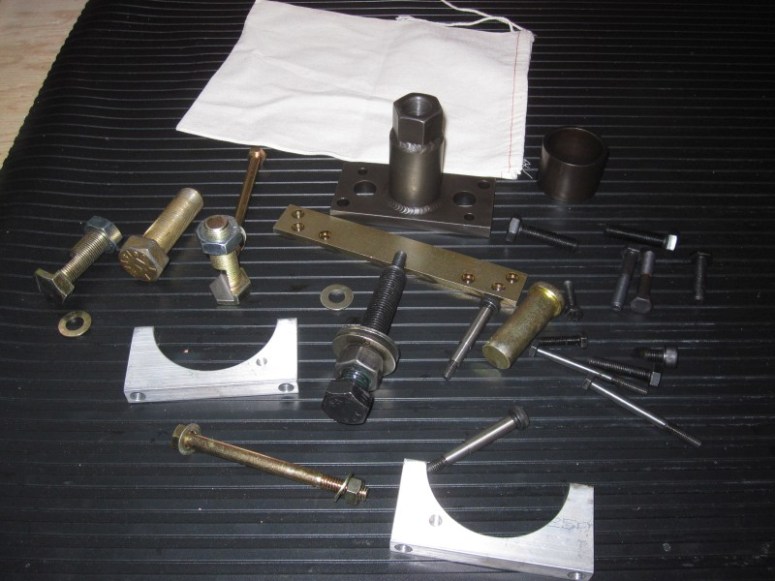
The first step is to have a good look at the goodies included in the Cycleworks “Many-in-one” tool. The included tools certainly have a solid feel to them and inspire confidence for this amateur wrench-wielder. I took the time to have a look at most of the “bottom end” video as well. This thing looks like it has “period correct” filming technology, wardrobe and hairstyles but is quite good at illustrating the steps involved in taking a /2 motor apart.
Because the motor was already out, we were able to start at the camshaft removal section. Unfortunately our Many-in-one tool came without instructions and the one used on the video has some different parts that ours doesn’t have. We sent a note to Cycleworks and got an answer a short time later, along with a pdf file with the instructions, diagrams and all.
Where the inner guts of the motor will all be hanging out, we decided that it would probably be smart to replace the crank bearings as well. The front one is pretty cheap, but the special rear one isn’t at $ 250 from Max. I suppose we could have waited until the old one was out to have a look at it before deciding, but it isn’t much fun to get stalled in the process while waiting for yet more parts.
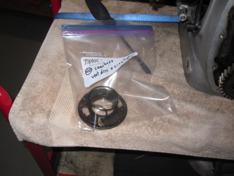
The very first step was to remove the camshaft vent, which is held in place by a clipring. 2 screwdrivers and some needle nose pliers made this an easy “bag and tag” job
Then it was a simple matter of using an impact driver to remove the 4 bolts which are behind the timing gear. You can only see 2 at a time with this “newer model” 1961 bike, so you have to rotate the crank a bit to see the other two.

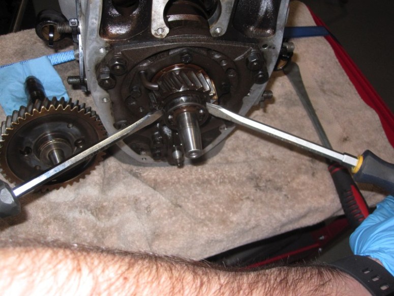
Once those bolts are removed, we braced the pulling tool using some long bolts screwed into the case. Here we see the tool in place. Notice the lube on the nut to facilitate pulling the camshaft. Also notice the lifters have been removed to be sure they didn’t interfere with the camshaft removal.
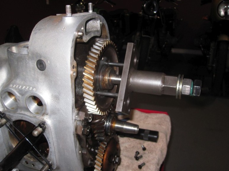
A bit of heat applied to the back of the case to dilate things a bit…

Then basically holding the bolt in place whilst tightening the nut to effectively pull the camshaft out. It didn’t require much grunt, things came out quite smoothly.
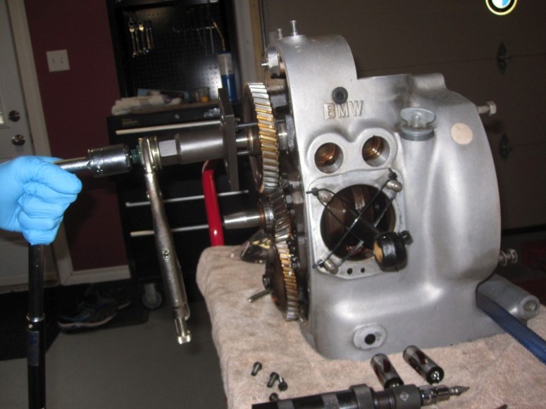
Then simply remove the 2 bracing bolts and pull out the camshaft.
You can see the rear camshaft bearing remained nested within the rear of the case.

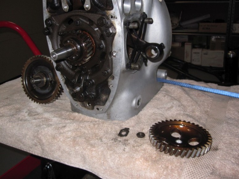
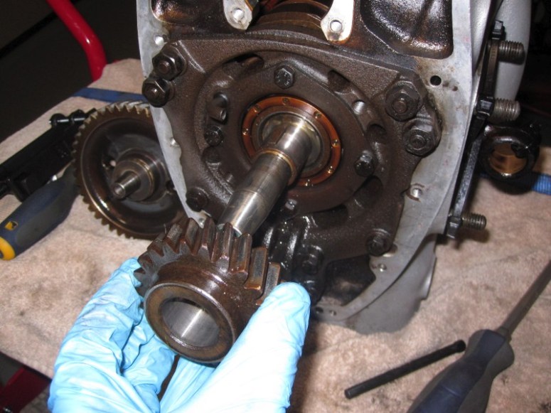
Next on the list is the oil pump gear, unbending of the washer then unscrewing the odd (opposite tread) 14 mm nut, followed by a puller

It came off easily without incident
Next is the front crankshaft bearing. The video shows using tire irons to start it off, but mine was recessed too closely to the crankshaft gears for this, so I had to resort to 2 screwdrivers. This was set in there quite tight, I had to heat it up with a heat gun first
Once started off a bit, I was able to use a bearing puller to finish it off
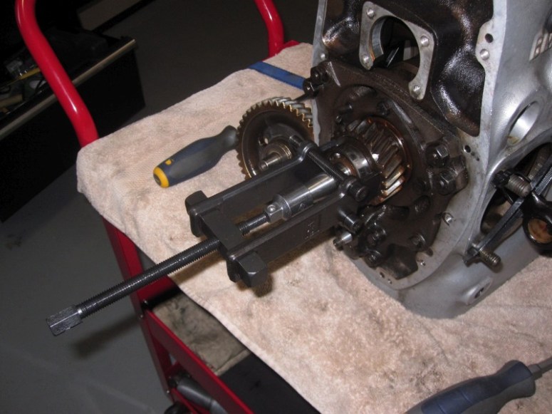
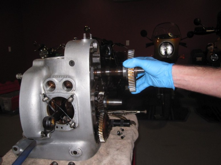
Next was the big crankshaft timing gear. This required the Many-in-One tool. Mine didn’t have any spacers nor any circlip between the gears and the bearing.
Inserted the tool and it did take quite a bit of torque, but finally I won
Well, that’s all the time I had today. Happy with progress
November 28th 2016
I was hoping to get this part done over the weekend, but I couldn’t find a 1-5/8″ socket in any of the stores that are open on weekends. I finally got one today, along with a 1/2 to 3/4 inch drive adapter and gave her my best with my breaker bar
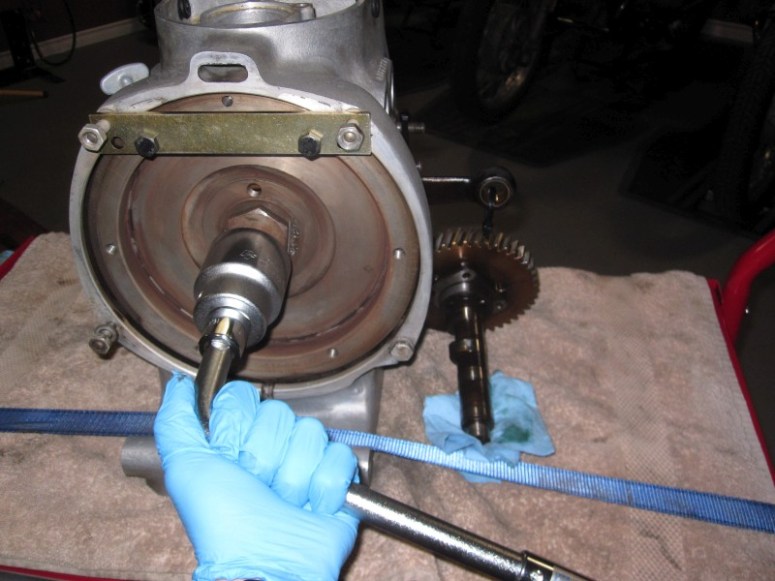
After a few good grunts on my end, I decided to do the ultimate sin and slap on this regular socket on the impact wrench

A few short Raaaaaat-a-tat-tat’s later and we have this
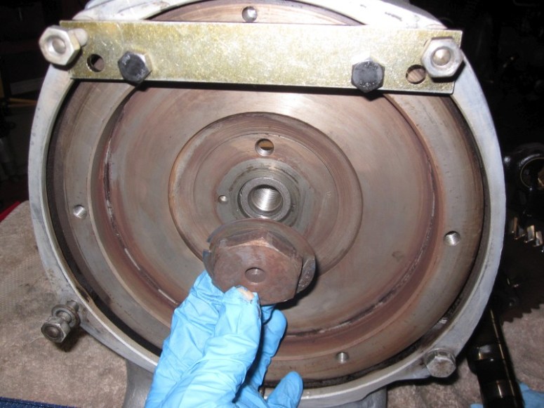
Put on the puller, and again, was surprised at how solidly the flywheel was stuck on there, cranking on the puller then “POP!”, off it came
I left some sharpie marks on the flywheel before removing it, but later realized this is completely un-necessary, as the flywheel will only fit on the crankshaft in one position.
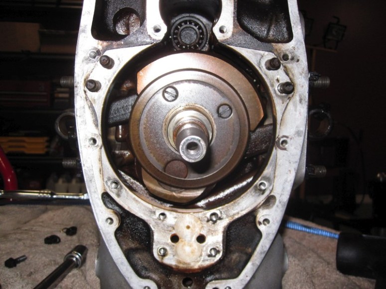
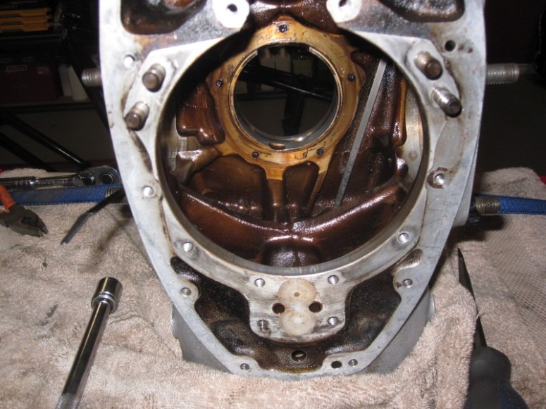
Once the flywheel was removed, I was granted the view of a leaky rear main seal, with the resulting sploodge of oil all over the casing
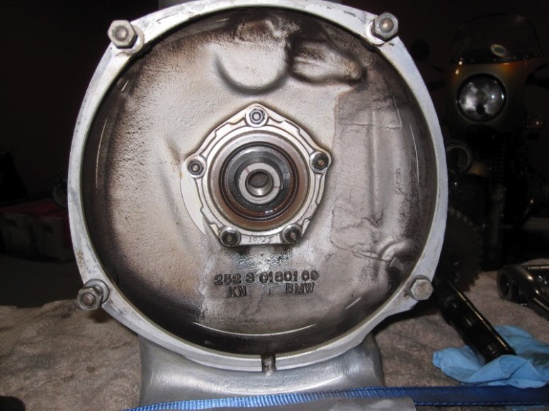
This was cleaned up rather easily with some Pine-Sol followed by a few shots of brake cleaner for the stubborn spots.
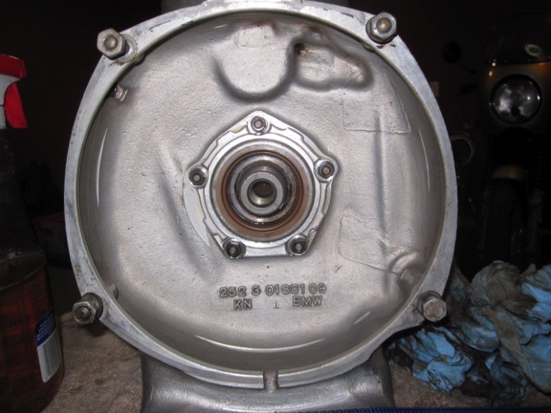
The flywheel was cleaned in the parts cleaner with mineral spirits and all is good in the world again! That’s all the time I had today, maybe 30 minutes or so…
November 29th 2016
Tonight’s challenge was to tackle the front bearing carrier.
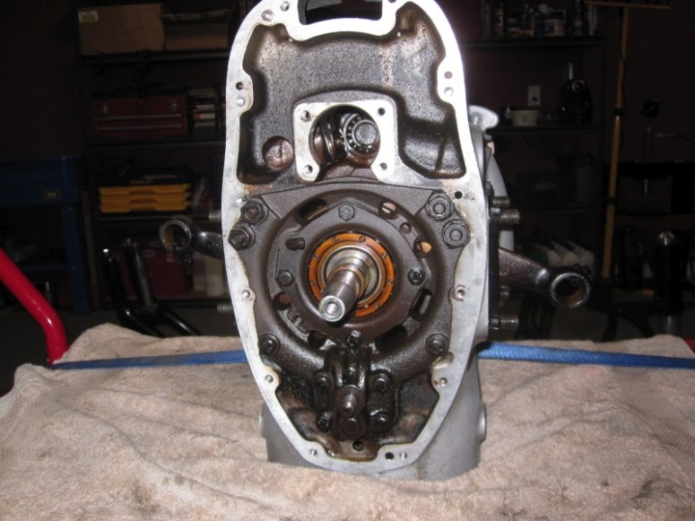
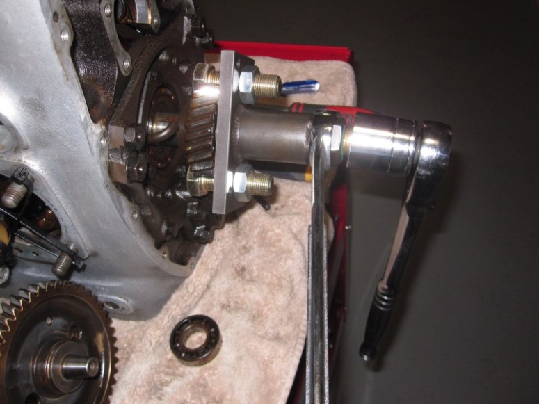
It was the simple matter of removing the 10 supporting nuts and bolts holding the carrier to the case, but leaving those 4 bolts that support the front bearing

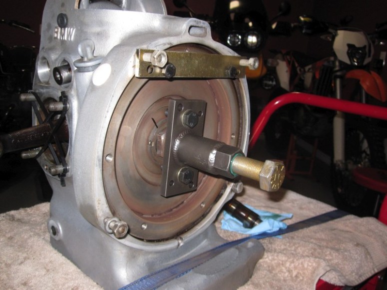
Next step was to install the Many-in-One tool onto the front bearing carrier and screw in the big puller bolt

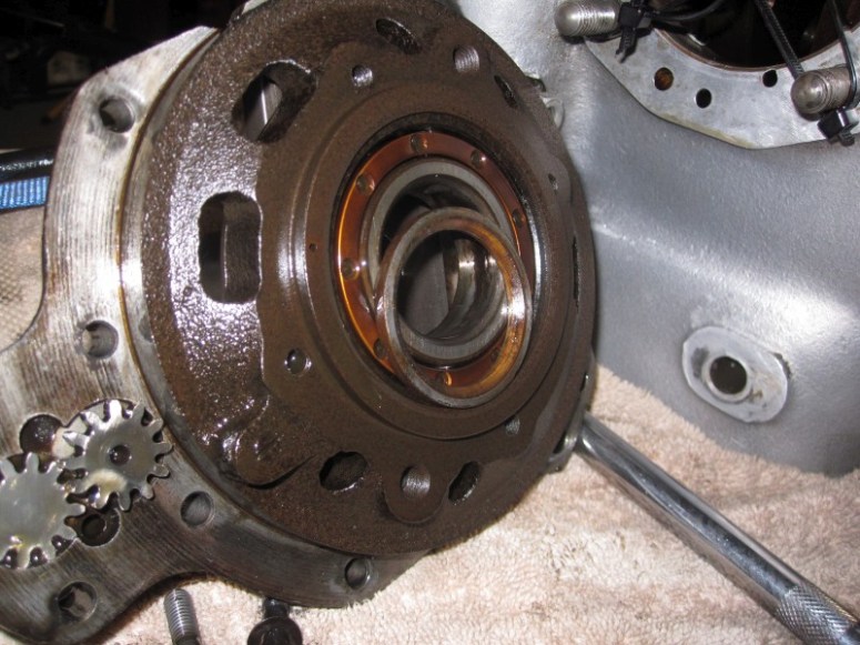
No big “pop” this time, the carrier just gently moved forwards as I was screwing in the big golden bolt. Here is a pic of the backside of the carrier, the curved part of the spacer faces the crank. Notice the little oil pump gears at the 8:00 position in the picture. Careful not to drop these
Finally we get the first view of an actual slinger!

The removal of the front slinger was fairly straightforward, with the help of an impact driver.
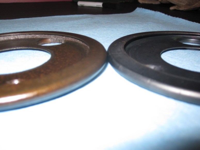
Here is a photo of the front slinger on the left, compared to a new slinger on the right. As you can see the crud was starting to reach the hole where the lubricating tunnel to the connecting rod bearing goes. I couldn’t see any crud within the passage to the connecting rod bearing but it wouldn’t have taken much longer I’m sure.
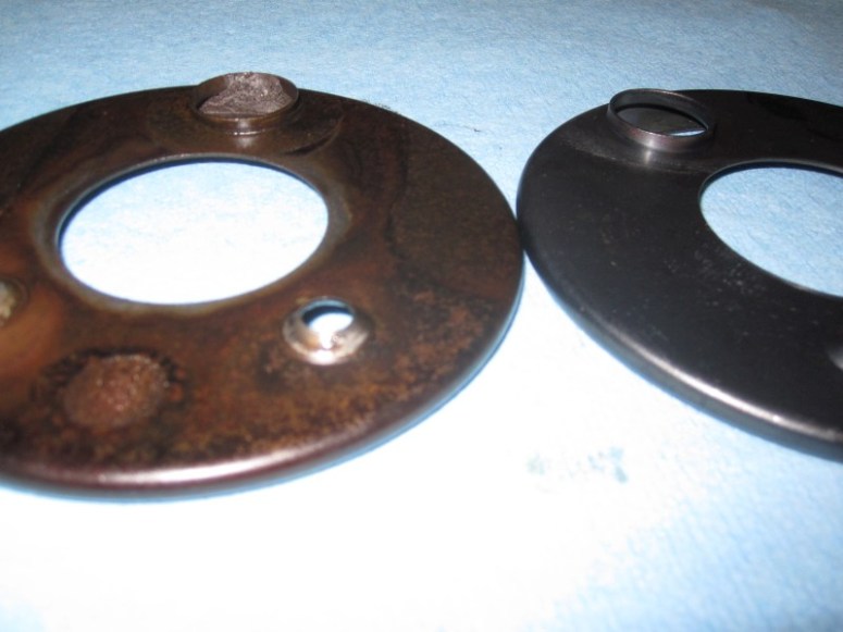
Here’s a view from behind. You can easily see the accumulated crud making its way up through the passage.
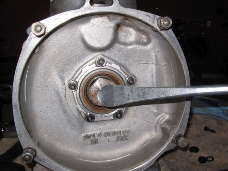
The next step is to take out the leaking rear main seal. The flywheel bolt protects the crank while the seal gets pried off with a tire iron. Careful not to scratch the sealing surface on the case. In this case, the seal was quite resistant to being pulled out. It worked better after a bit of heat and a tire iron that had more of an angle to it.
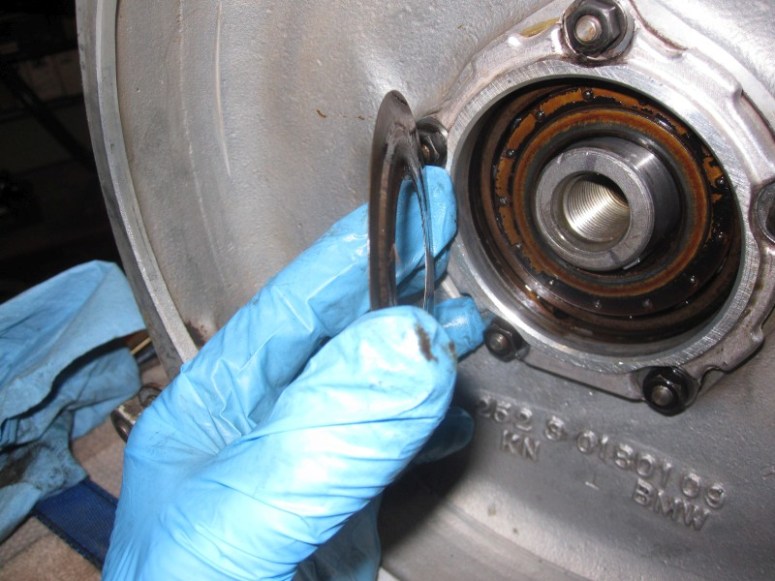
Then the splash ring comes off. The more central part of it sits right up against the rear bearing and the periphery is raised slightly away from the bearing.
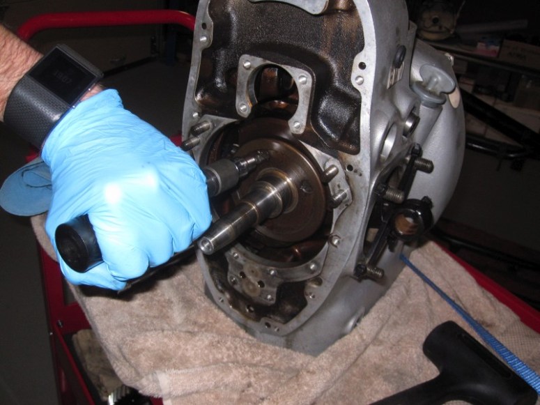
I was then able to pull out the crank and then I realized that the rear bearing had spun. It was loose on the crankshaft
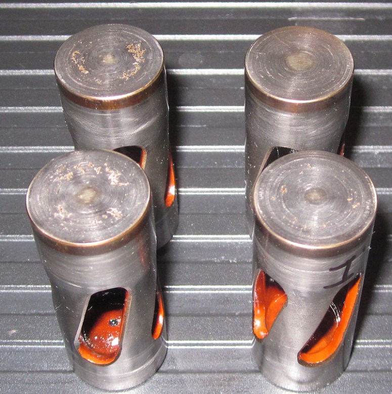
The rear slinger was removed the same way as the front one, with the help of a impact driver

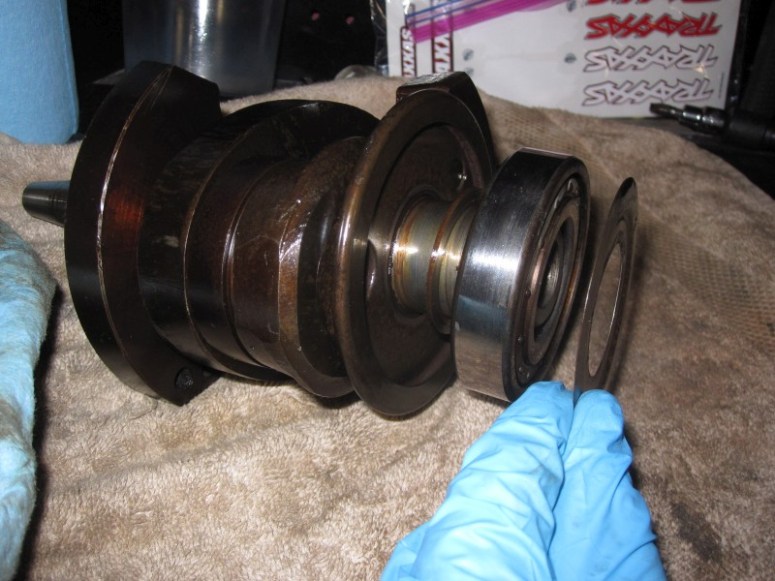
Here is a view of both slingers showing over 50 000 miles of accumulated crud. I’m happy to see that this involved process was done for a good reason. On top is a new slinger for comparison

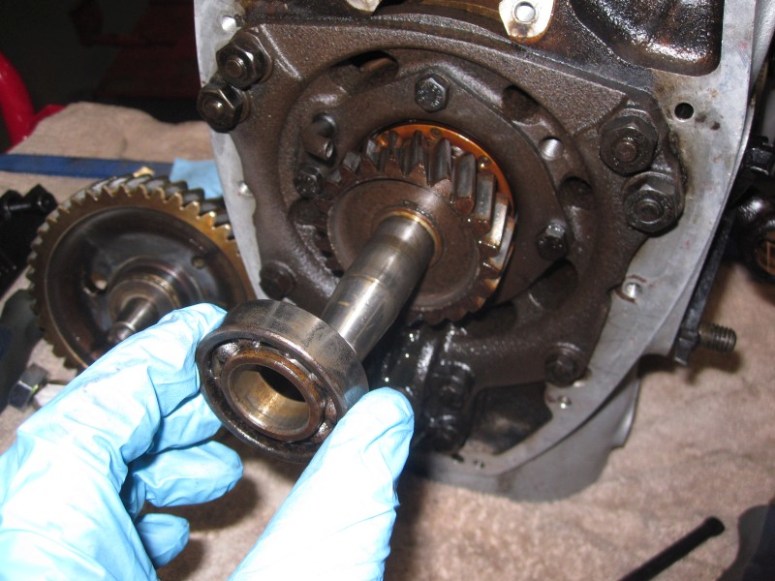
Just for fun, I had a look at the rear bearing again. It would slide on and off the crankshaft quite easily. I then opened the box containing the new rear bearing to see if this one too would easily slide on and off the crankshaft. To my surprise, I wasn’t able to get it on by hand. I didn’t start pressing it in or anything, but rather I just took a rough measurement of the inner diameter of the old bearing

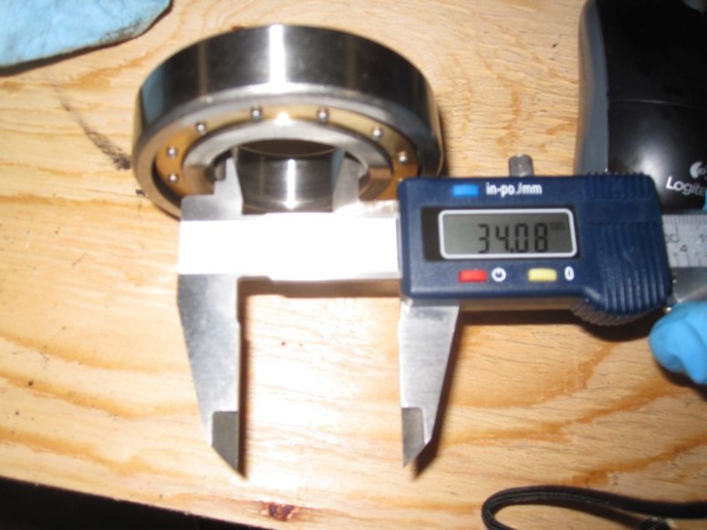
Followed by the same measurement of the new bearing
It might be wishful thinking but it appears that it is the inner aspect of the bearing that wore out and caused it to spin. I’ll be curious to see if the new one will fit tightly on the crankshaft or if we’ll have to send the crankshaft out somewhere for refurbishment.
Here’s a view of a much lighter case.
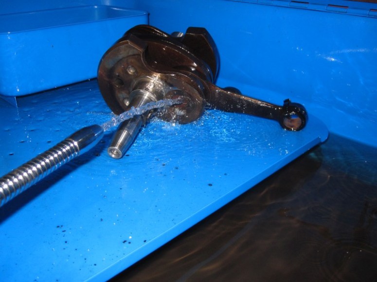
The next few days will likely be spent cleaning and measuring parts before attempting to put anything back together. The crankshaft in particular will get a nice long bath in mineral spirits to be sure to clean out all the passageways, followed by a careful inspection of the connecting rod bearing play.
December 2nd 2016
One of the main concerns at this point is wondering if the full slingers caused any sludge to find their way into the passages that let oil lubricate the connecting rod bearings. I took the time today to carefully inspect these passages and it appears that all is well.
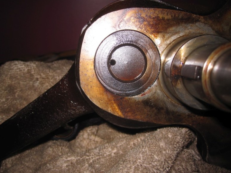
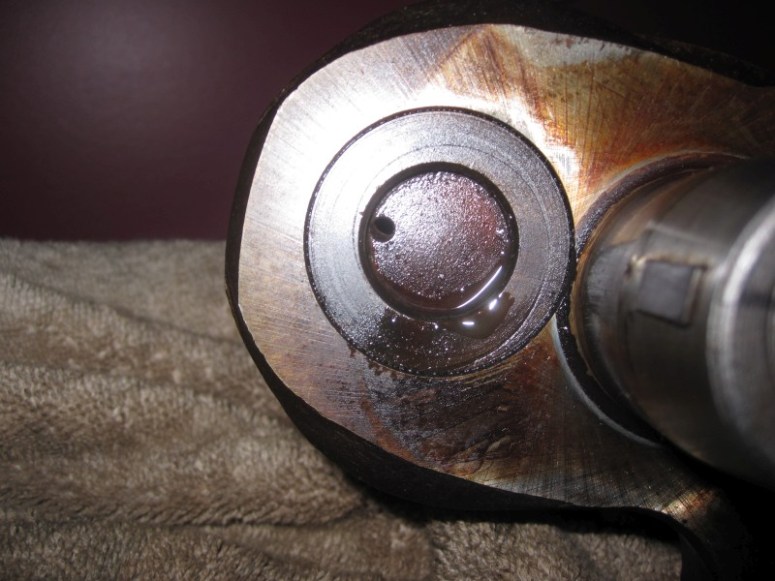
I’ll admit that it’s hard to tell from these pictures, but I also shone a light from behind and it was pretty clear to me that there was no grunge within these passageways. Nonetheless, they each got a good 5 minute shower with mineral spirits followed by a good 15 minute soaking in the tub.
After I was convinced things were sufficiently clean, I proceeded to measure the axial play in the connecting rods
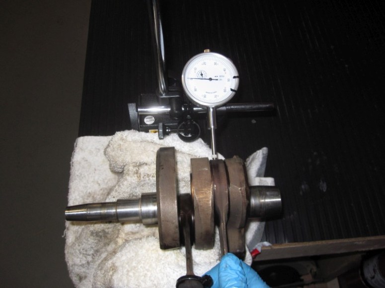
The axial play on the right rod was 0.00075″ (or 0.019 mm) and the left was a bit better at 0.0005″ (0.0127 mm). This is actually tighter than spec (0.07 – 0.1 mm). They really felt tight but rotating freely. I’m not concerned at all with the crank bearings. There’s a little bit of lateral play, but fairly slight.
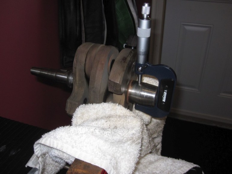
I also measured the area where the rear (spun) bearing sits on the crankshaft. The micrometer measured an average of 34.572 mm (6 readings)
The vernier caliper was a bit different at 34.97 mm
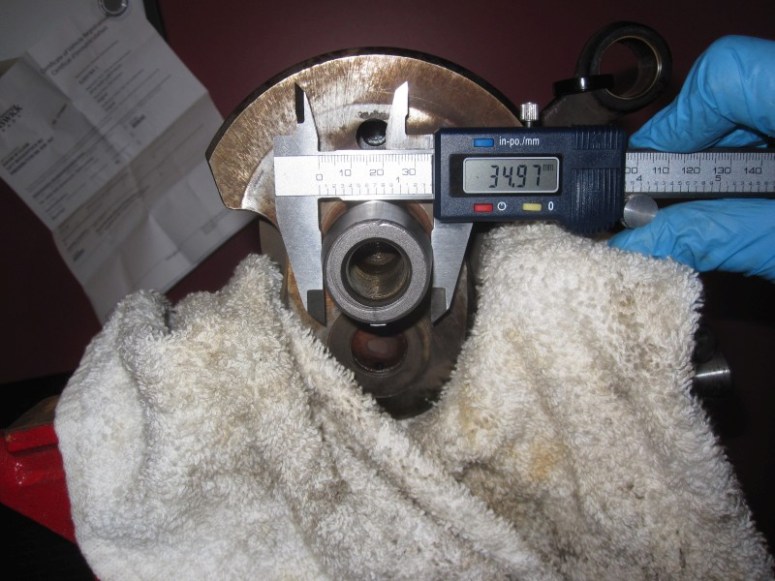
Spec according to Clymer calls for an interference fit of 0.015-0.025 mm here, Where I don’t have a really precise way of measuring the inner aspect of the spherical roller bearing, the vernier indicated 34.08mm on the new bearing, so the interference is probably in the ballpark of 0.48 mm. However, if you look at the old bearing it would appear to be within spec, so I’m thinking my inner measurements are maybe off somehow. I’ll try to re-measure the bearings to see if I can be more precise. I think on reassembly I’ll have a good idea if the bearing will be tight or not.
I also had a look at the lifters, some are more scored than others. They don’t look too bad in real life, but the photos seem to magnify the pitting