We’re getting closer !
Time to set the static timing. For this step, we’ll need some juice from the battery…
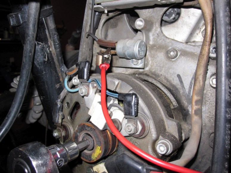
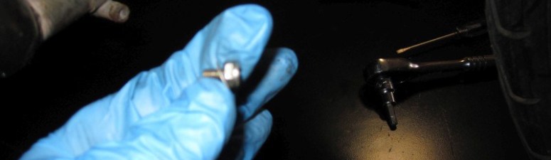
There are several ways to do this. The classical way is to wire a “buzz box” or even a lightbulb with wires soldered to it. I’m a bit lazy and never bothered to set up a “static timing bulb” so I just use a good old voltmeter instead. I did set up some leads with alligator clips to keep things attached though… One lead goes to the condenser…
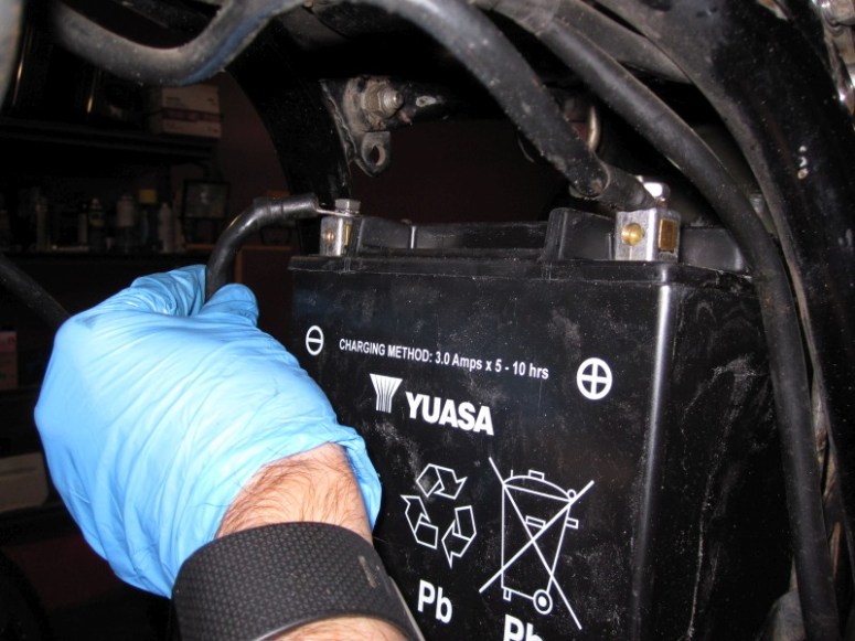
and the other lead goes to a good ground. The battery negative terminal is about as good a ground as you can get…

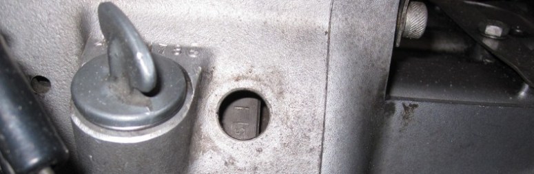
Next step is to turn on the voltmeter to DC volts and to measure the voltage as we are turning on the crankshaft. We must also turn the ignition to “on” to get power flowing through the points. The voltmeter should be reading near zero volts then as you turn on the crankshaft you can hear a click and the voltage jumps up to around 12 volts as you approach the “S” mark on the flywheel.

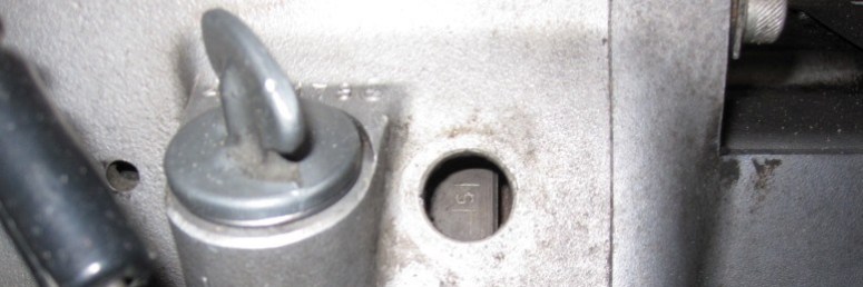
This is where the flywheel was on the first click. The important bit is to keep going round until you hit it again to check the other cylinder.
This is cylinder #2 (one whole rotation of the crankshaft later), notice that the “S” mark is not exactly at the same spot on the flyhweel. It is very difficult in points systems to get both cylinders timed perfectly. if the nose of the camshaft is bent by even just a little bit, the timing differential will be off by several degrees. The difference in both cylinders here is very acceptable to me.
The good news is that the timing was pretty much spot on. Had it not been, it would be a matter of loosening the screws on the points backing plate and rotating the whole thing clockwise or counterclockwise depending on if you wish to advance or retard the timing.
Next is to check and adjust the points gap. Wait a minute, what’s this ?
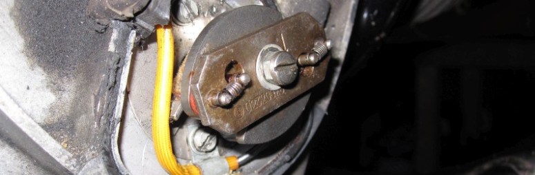
This slotted screw-thing holding the advance unit does not belong there… What has happened is that some ham-fisted person snapped off the nose of the camshaft while torquing that 10 mm nut…
What we have here is a slotted screw with a nut treaded into it…

At least someone had the decency to do a proper fix. I’ve seen much worse, such as just peening the camshaft tip to lock the advance unit in place. What they did was to tap the nose of the camshaft to accept a screw. This is very good and beats taking the whole motor apart to replace the camshaft. Here below we see the tapped nose of the camshaft with the advance unit removed.

The points can then be adjusted. I use a device that slides over the camshaft nose to mimic maximum lift from the advance unit. This makes it easier to check the points gap and to get it perfect.

