December 2nd 2016
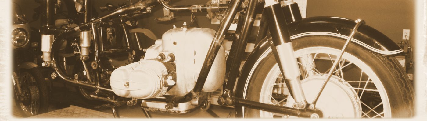
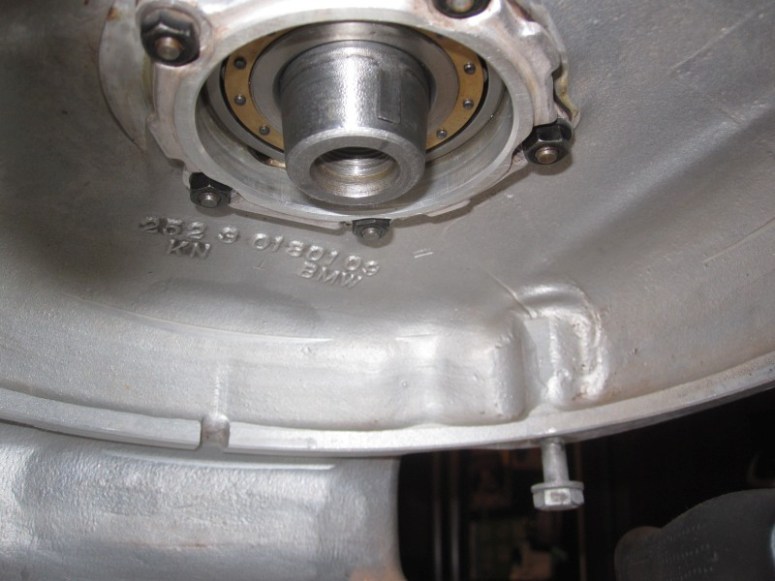
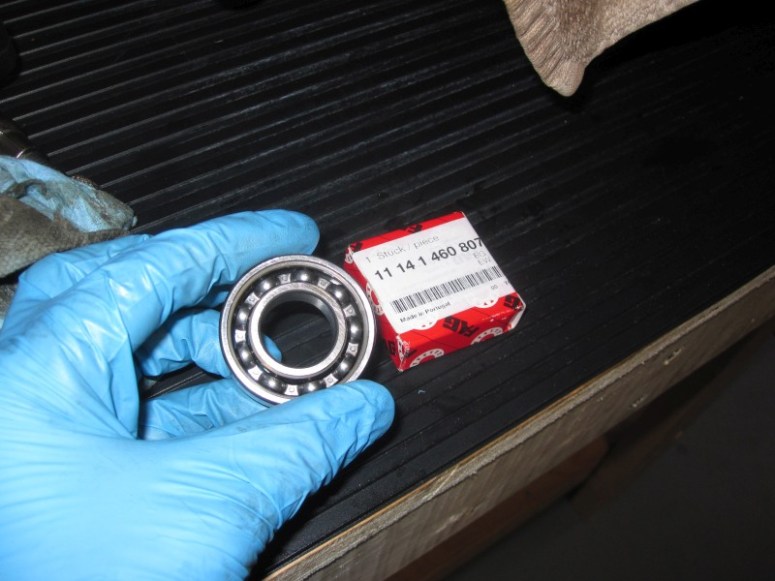
I had a bit of time tonight, so decided I would see about replacing the front crank bearing from the carrier. First step was to remove the 4 bolts that hold the bearing within the carrier
Then I heated the carrier and the bearing before putting them on the press and simply pressed it out.

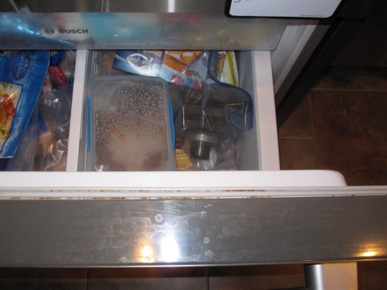
I then put the new bearing in the freezer while I heated the carrier up again with the heat gun. The new bearing slid in with the help of a few taps of a rubber mallet. I then re-bolted the retaining plate onto the carrier.
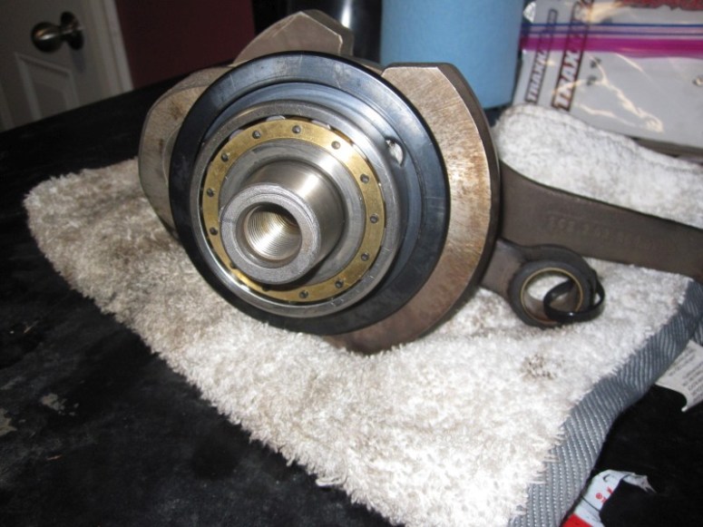
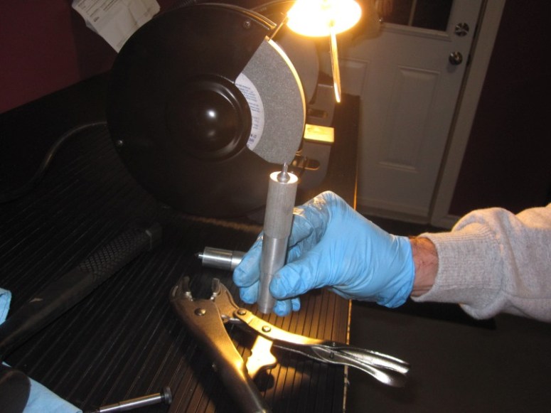
I also pressed in the spherical rear main bearing onto the crankshaft. I used the old bearing and the flywheel bolt to get it started. It did require a fair bit of torque to set it in place. Once started, I used the spacer from the Many-in-One tool to drive it up against the rear slinger. At this point I’m not at all concerned about the bearing spinning, it took a fair amount of torque for it to seat up against the spacer. It’s not moving from there anytime soon.
December 4th 2016
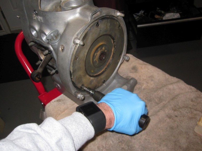
OK, I’m kind of stuck. I can’t re-assemble the crank until I have the rear main bearing aligning tool, as I’m not in the mood to take risks with a $ 225 USD bearing. I decided to see if I could clean up one of the heads tonight
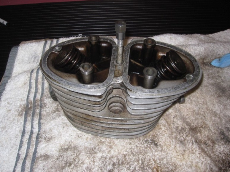
A valve spring compressor was quick to take out the removable bits from the left head
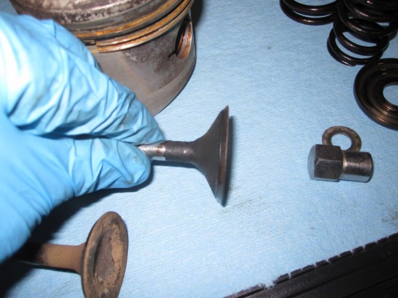
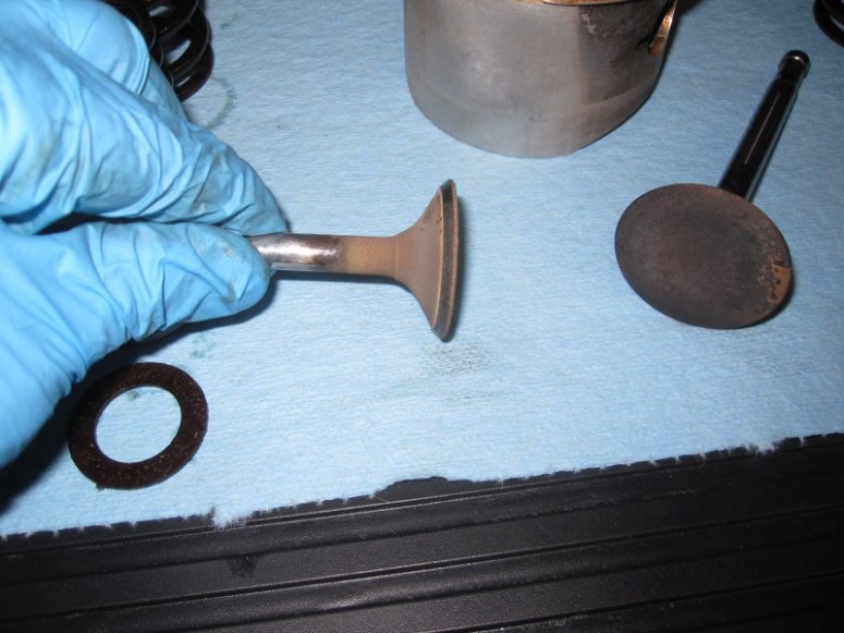
as far as I can tell, the seats don’t appear to be recessed in the head, and at first glance the valves don’t appear to be in too bad of a shape
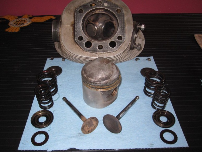
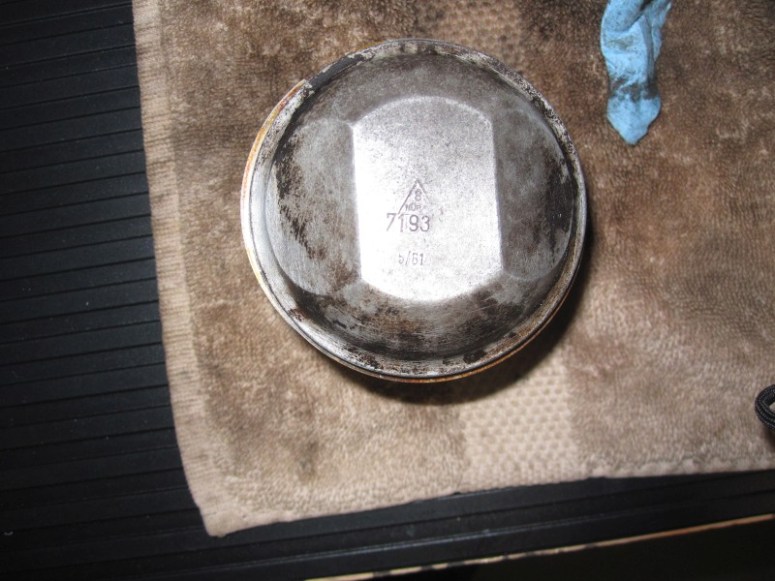
The piston (left side original) appears to be a 71.93 mm, standard piston sizes according to Max are 72, 72,5, 73 and 74 mm.
The left cylinder also appears to still show some crosshatch
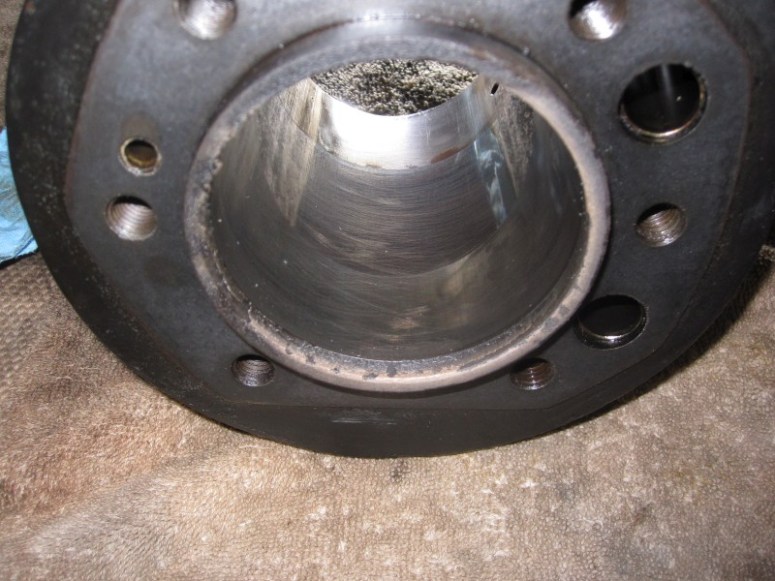
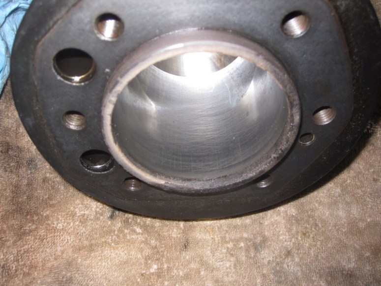
The parts are in the washer overnight, but so far, this side looks pretty good. Once cleaned there will be some measuring taking place to see if all is really well.
December 5th 2016
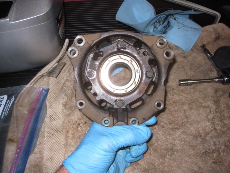
We didn’t order the CycleWorks special rear bearing alignment tool but I was questioning if this was really necessary. The idea is because it is a “spherical” bearing that it can be hard to get it lined up properly with the back of the case without the special holder that keeps it straight. I thought I would experiment a bit with the simple principle that metal expands when hot (in this case 300 Fahrenheit for about 45 minutes, hot enough for spit to sizzle)…
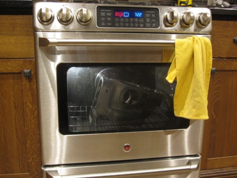
… and contracts when cold (all day in the freezer)
Helped with a pair of oven mitts and a bit of contortions to avoid burning myself on the hot metal, the rear main bearing slid right in without any persuasion required from Mr. Hammer.
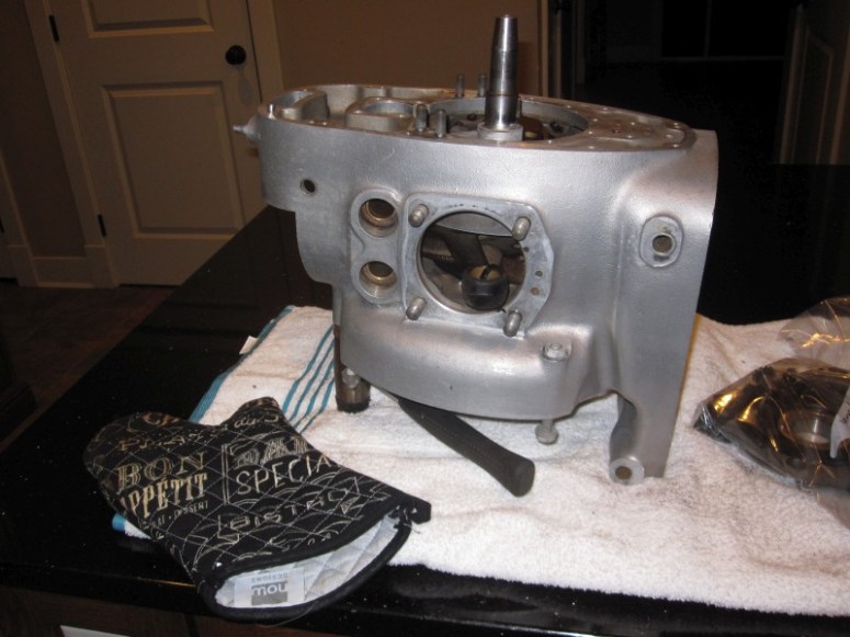
I kept the crank vertical while the metals agreed to settle to a common temperature, as I didn’t want the crank to lean downwards until things were tight back there.
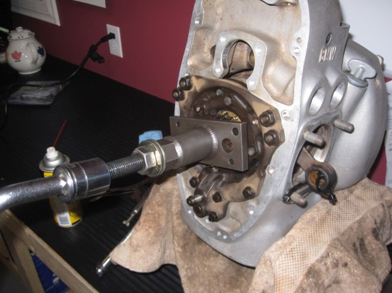
After things had cooled down and the crank was tight up against the rear of the case, off to the garage I went. The first step was to install the front slinger
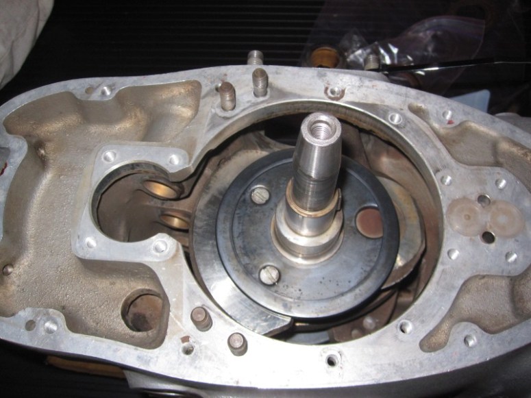
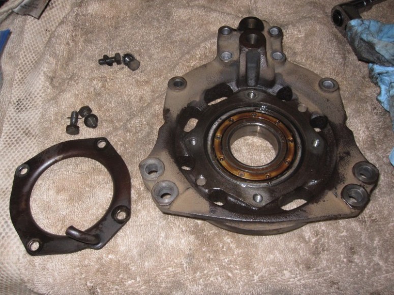
and hammer a small metallic sliver in the screw slot to “lock it in”. Then came the little spacer, beveled side facing the crank followed by the front bearing carrier onto the case. Unfortunately, as I was cranking down on the Many-in-One tool, instead of driving the front bearing housing down into the case, it was pulling the rear bearing out of its seat. After a few choice words, I brought the whole thing back into the house and another stint at 300 degrees. While in the oven the front bearing carrier gently slid into its place in the case and the rear bearing went back into its home. A few tightening turns with the many-in-one tool to snug everything up and then it was just a matter of buttoning up the 4 nuts and the 6 bolts in the front…
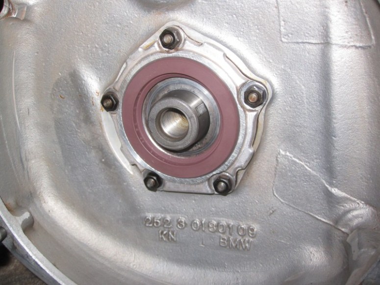
Then, off to the rear again, installed that oil splash ring over the bearing, concave side outwards (I know, no picture of it here, forgot to snap a pic when installing it. Imagine a thin metallic plate hiding the bearing on the pic below.
Then decided to install the rear main seal, as I figured that it would be easier to install in the warmed up, dilated hole… No special tools required, it slid in by hand and tapped in place with a wood block and a rubber mallet. No drama here either.
The rear of the case is now buttoned up, next step will be reinstalling the front gears.
December 9th 2016
Time to move back to the front of the crank. First step is re-installing the crank timing gear. This was heated with a heat gun then pressed onto the crank with the special Many-in-One tool. Yes, that’s a teapot in the background. Wrenchin’ with my good friend Earl Gray…
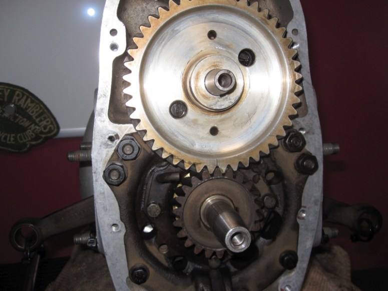
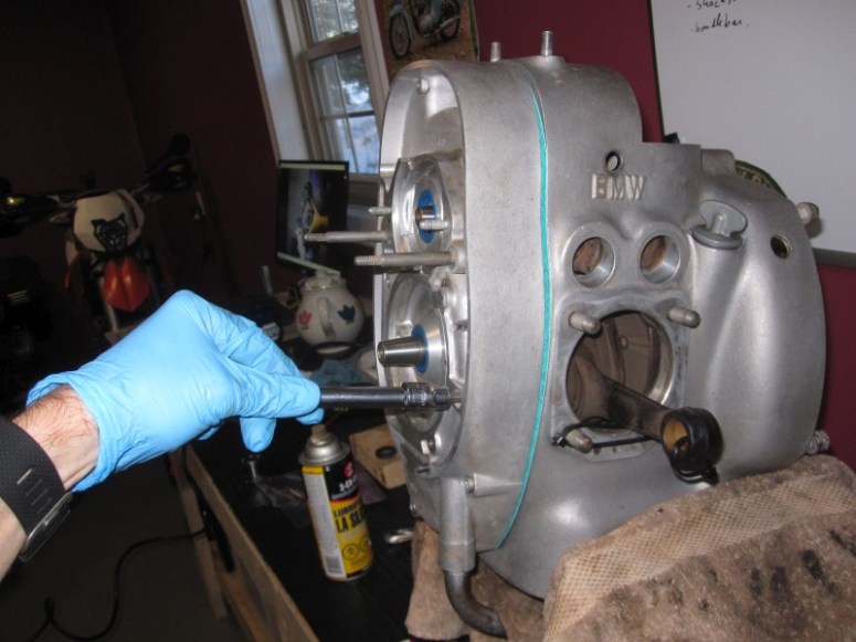
Then the camshaft gets installed. This piece slips right in and gets screwed in position with those 4 small screws which gently drive it back into the case
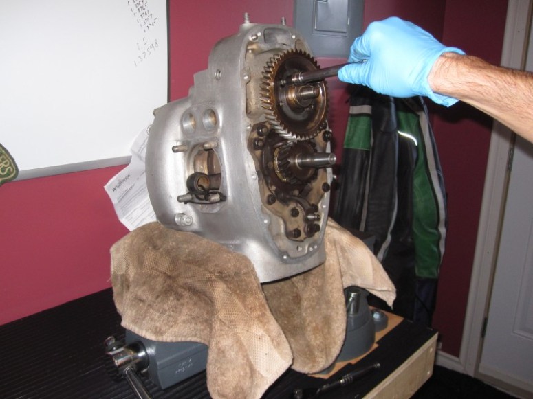
There’s a mark on the camshaft gear (at 6 O’Clock position) which needs to line up with a similar mark on the crankshaft gear (at 12 O’Clock position)
Next the vent disk is oiled up prior to installation then held in place with a circlip.
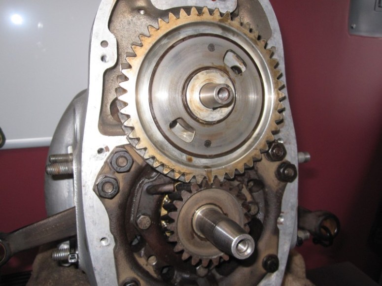
Then it the oil pump gear that slides in. It gets held in by that special reverse-tread 14 mm nut.
Which in turn is locked in place by a bent clip.
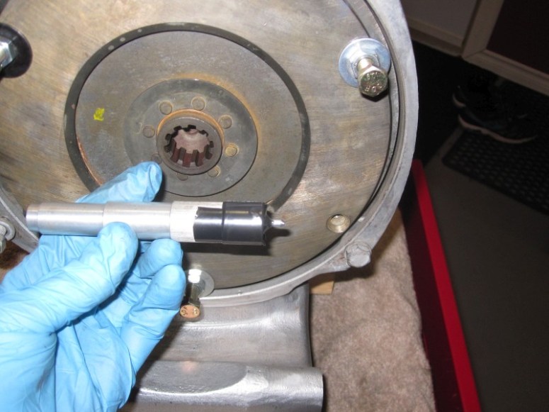
At this point I checked that the crank turns freely with no binding. Then comes a new replacement grooved ball bearing.
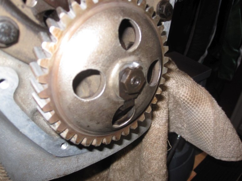
This puppy was heated up with the heat gun…
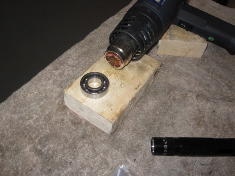
Then just slid in place over the nose of the crankshaft. No special tools needed.
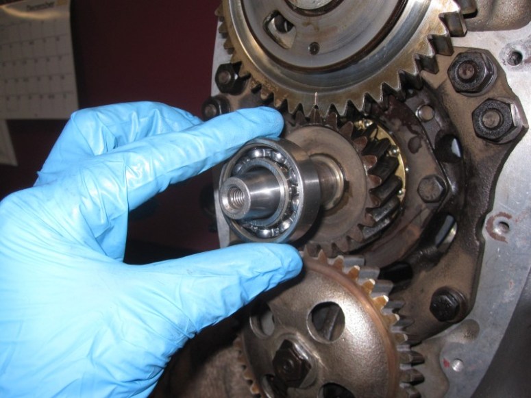
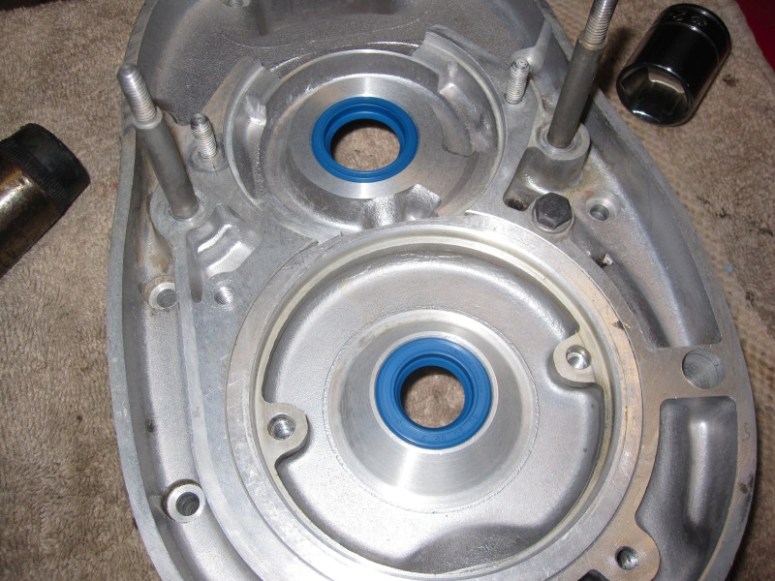
Next the old oil seals were removed from the timing case (Right side), their new replacements waiting on the left.
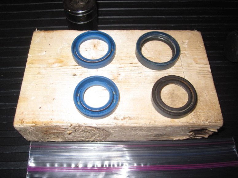
The case was heated again with the heat gun, and the seals slid easily in place.
Then a new timing case gasket was installed over the bolts on the cover before meeting up with the case. The 12 bolts were tightened in a crisscross fashion to set the heated case onto the crankcase.
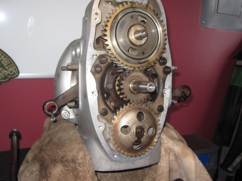
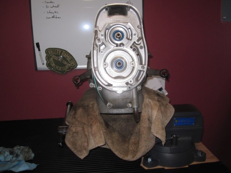
And this brings us to today’s conclusion with the front end all buttoned up.
December 10th 2016
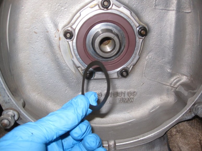
Time to finish off the rear of the engine. First step is to put that spring washer back in there
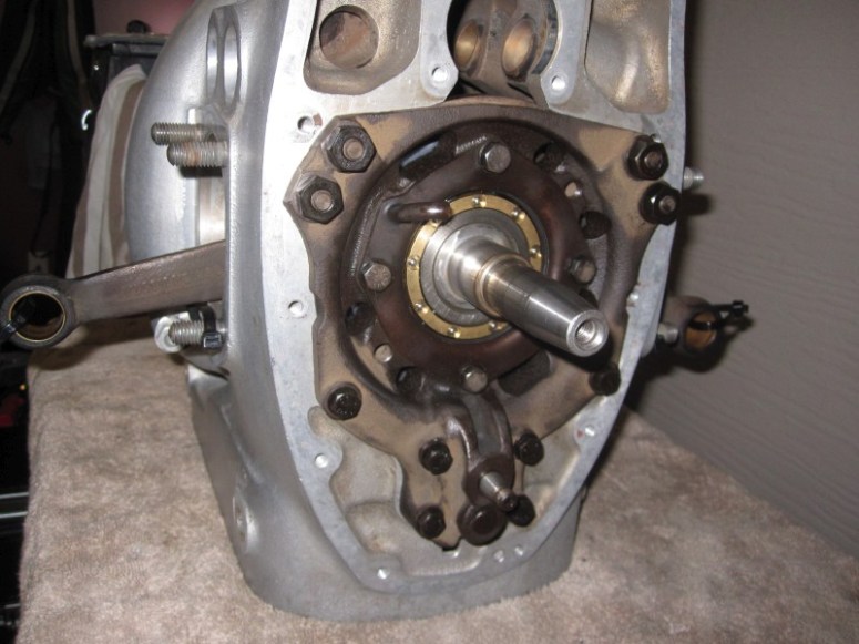
Then the flywheel goes back on
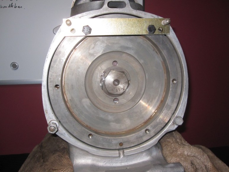
Then torque the big nut to about 50 lb-ft then check the runout on the flywheel
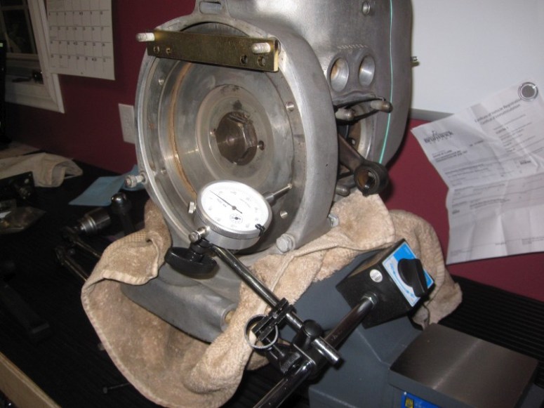
Spec calls for 0.004 inches of runout. This flywheel has about 0.008 inches. At $ 650 USD for a new flywheel, I think we’ll see how this one behaves in real life before switching it.
After checking the runout the next step is to torque down the flywheel nut to 123 lb-ft of torque. That is one tight nut !
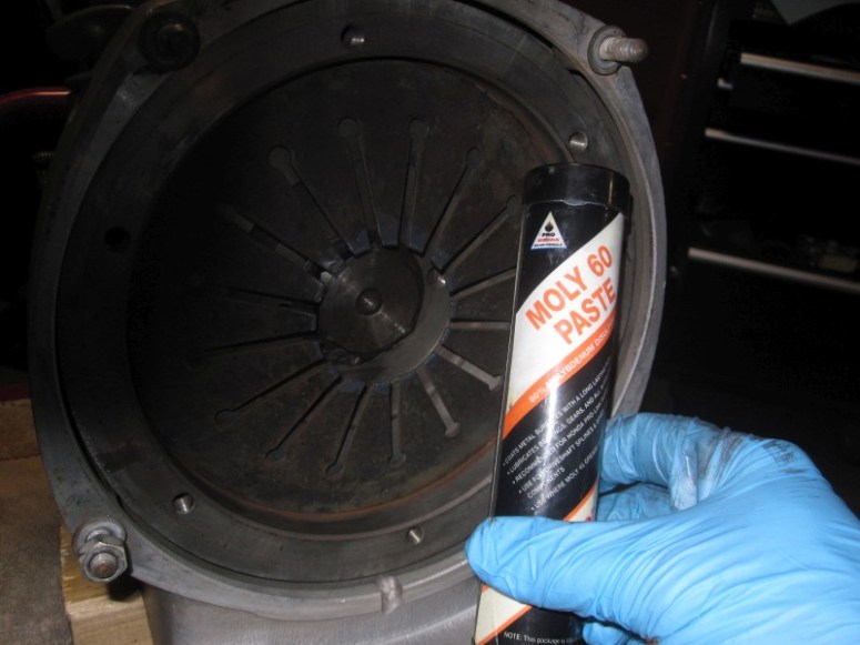
Then it’s time to install the clutch parts. The spring goes in first, and I applied a bit of moly paste onto the tips of the spring to make it slide easier on the clutch carrier.
Then the clutch parts go in with the 3 special “holder bolts”
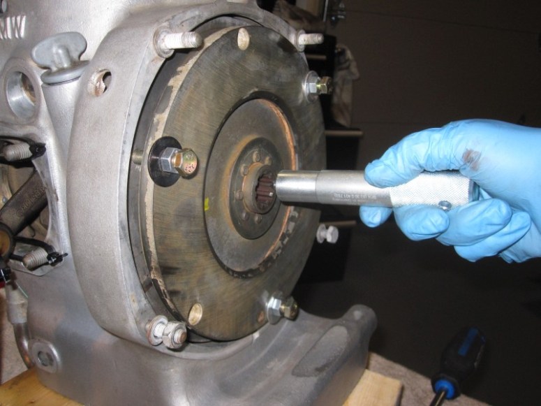
Followed by the clutch centering tool. Ikes ! the centering tool I got for my /5 is just slightly too big to fit in this /2 clutch splines. Gonna have to make my own.
Found a pushrod drift that was just the right size, then ground down a screw
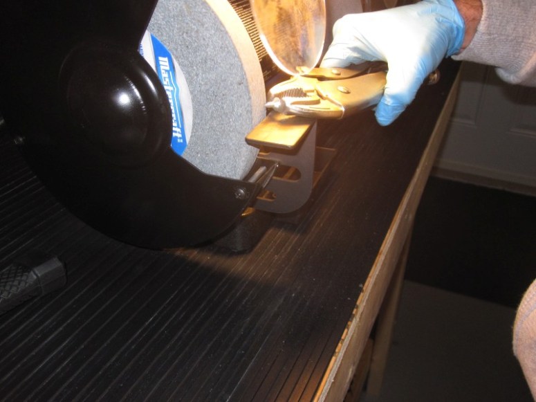
and installed that centered on the drift
A bit of electrical tape and it was fairly secure
Good enough to be used to get the clutch pretty well centered into the carrier before tightening those 3 bolts.
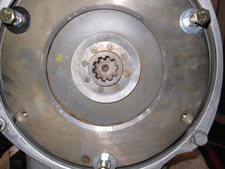
Here’s a pic of the lined-up clutch. It doesn’t look too well aligned on the picture, but it’s because of the camera angle. It’s pretty much centered.
Next step is to get the clutch carrier bolts in. First tighten the 3 in the empty slots, then remove the longer bolts and replace them with the short ones.
and finish ’em off with an impact driver.
That’s it for the crank re-install !
December 16th 2016
Once everything was re-installed, I felt there was a bit too much drag on the flywheel. After a bit of research and advise I disassembled most of the work I had done to find out that the rear main bearing had somehow migrated a little bit forward in the housing and when I was tightening the flywheel it was pulling it against the rear main seal. After some fiddling I got most of the drag taken care of. I also was instructed on how to install the flywheel to get rid of most of the wobble. This consisted of tightening it in 20 lb-ft increments while checking the runout and “pulling” the low point by rotating it and screwing the flywheel to the blocking plate. I made a little youtube video to show the final runout and drag on the flywheel.
