18 February 2017
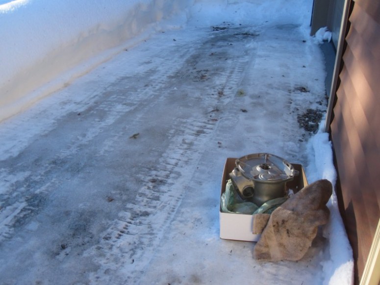
The output flange holder / pulling tool having arrived, it’s now time to open up the transmission to try to find the culprit that left metallic chunks in the transmission oil. The bike was riding and shifting fine, no weird noises coming from the transmission. However, the small chunks of metal looked suspiciously like pieces of a disintegrating bearing cage, so better address this now rather than wait for a catastrophic gearbox failure on the road.
before diving into the transmission, the kick start lever and the shift lever were removed, using some heat, then loosening the retaining pin nut until it was flush with the top of the pin. After this it was only a matter of a good whack on it with a hammer to get it started. The pins are tapered, so They do not just slide off, they need to be encouraged out a bit with something solid.
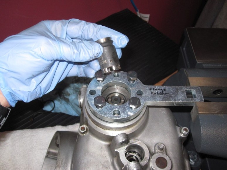
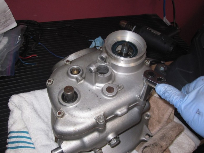
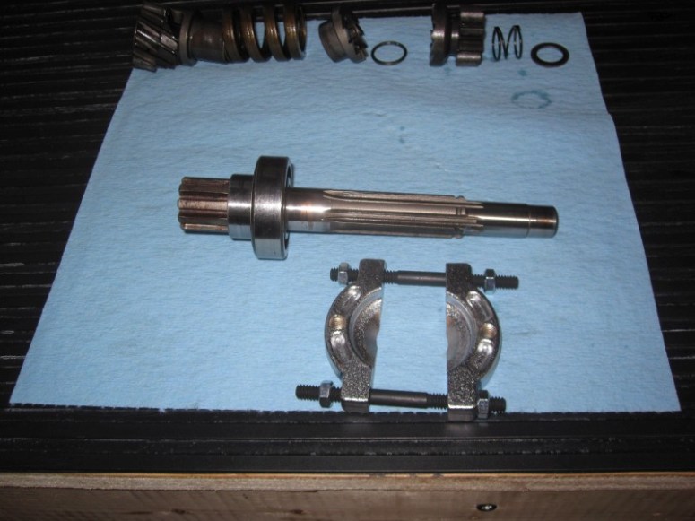
Here is a pic of the Cycleworks output flange puller bolted to the flange. In my hand is the special “small” crown bit to extract the nut while the flange holder prevents the flange from spinning.
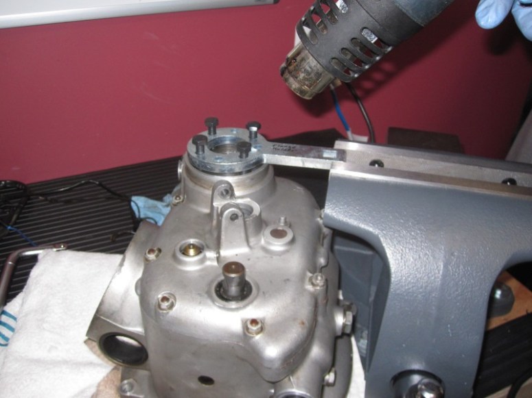
After things are held securely in the vice, some judicious application of heat will help coax the nut off of the output shaft. It can be said in general that heat and /or cold application makes pretty much every aspect of taking things apart or putting things back together that much easier.
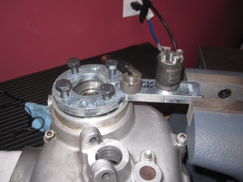
After not too much grunt work, the crown nut came off. Again, the Cycleworks parts quietly doing their thing without fuss.
Next the extra flange pulling parts are bolted on, and after lubing the extractor bolt, the flange gets pulled off using a breaker bar on the flange holder and tightening up the extractor bolt with another wrench.

Once the output flange is removed, we can now remove the small 10 mm nuts holding the transmission case closed.
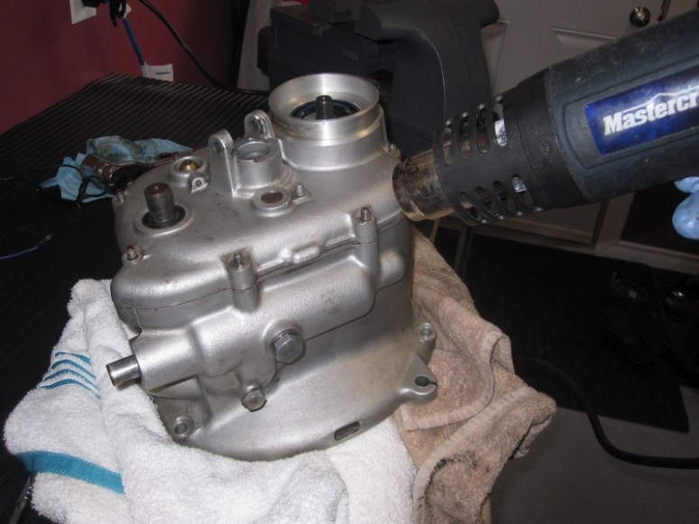
Again heating up the case cover helps removing it. With the nuts removed, it is a matter of tapping the cover in a few select areas that have tabs built for this purpose with a rubber mallet.
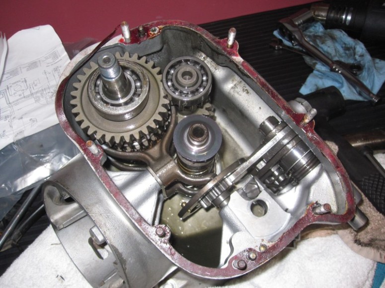
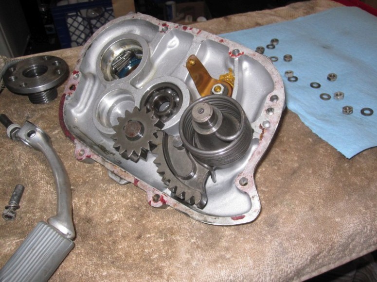
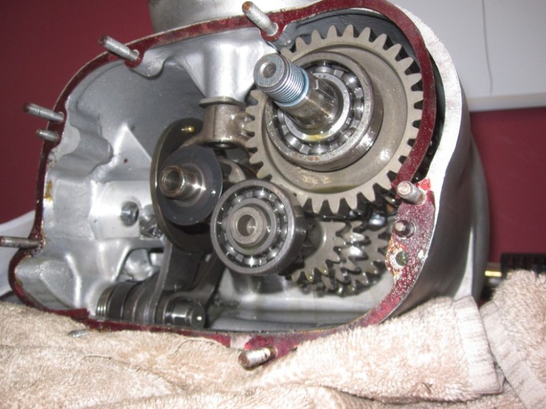
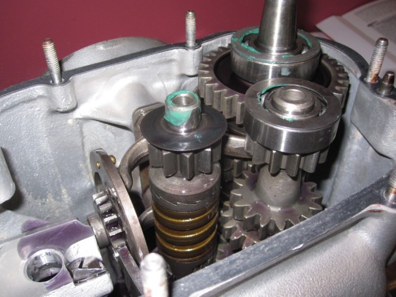
So now the cover is off. This gives us a good view of the output shaft (leftmost one in the pic below), this is the one that had the output flange attached to it. To its upper right, we see the intermediary shaft (the one with the bearing on top) and below it sits the input shaft, which pokes out the front of the transmission and connects to the clutch splines. All 3 shafts spun freely without any apparent notchiness.
With the cover off, we can see the kick starter gear as well as the neutral indicator switch. The yellow stuff is some form of sealant used to keep the switch oil-tight.
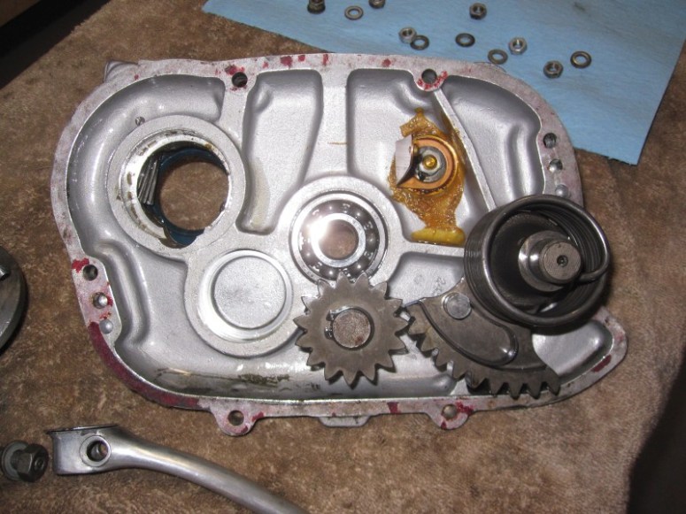
Here’s another view of the case cover, we can also see the big spring that pulls the kick-starter back to position once the kicking is over
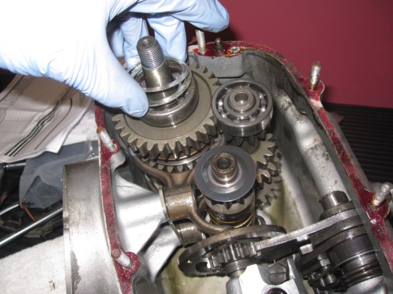
In my hand are a couple of shims. These are a source of anxiety for me as things must be shimmed just right on re-assembly for things to work right
Here is a washer also that I will do my best not to lose.
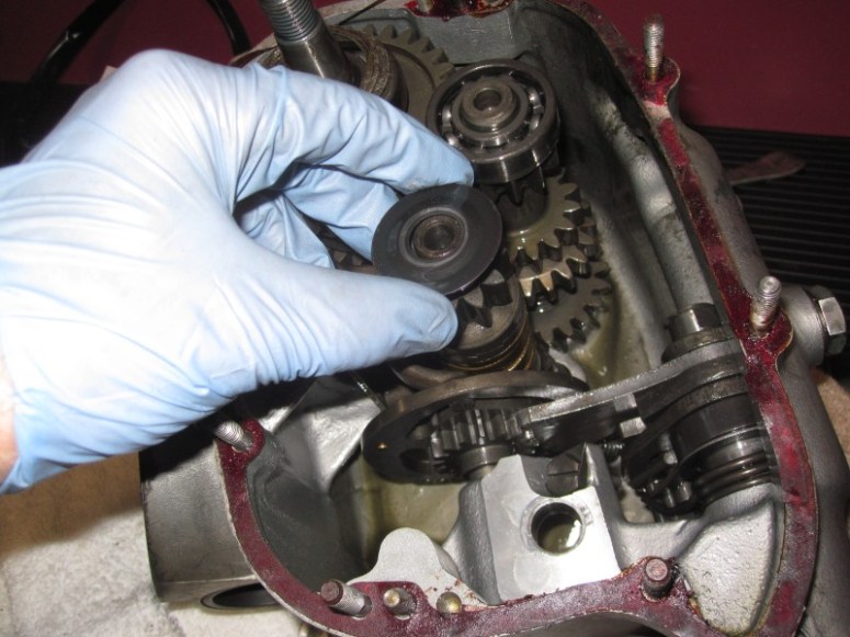
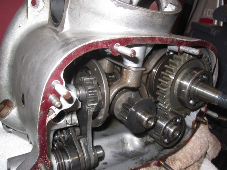
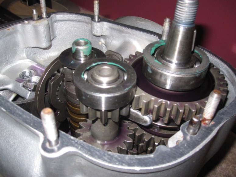
Here is a view of the shifting forks, well at least one of them. They are held there by an allen bolt that lies under the air filter. Unscrewing either one of these bolts without knowing what they are for with the transmission in place leads to a dangerous and expensive turn of events. No fear here, they must come off to remove the shafts.
This is where I was sort of hoping to see a bearing that was in the process of tearing itself apart. Of course it couldn’t be so easy. At this point I’m suspecting the forward input bearing, as I know that the rear crankshaft bearing had spun, therefore likely putting strain on the input shaft bearing. We’ll see if this premonition holds true.
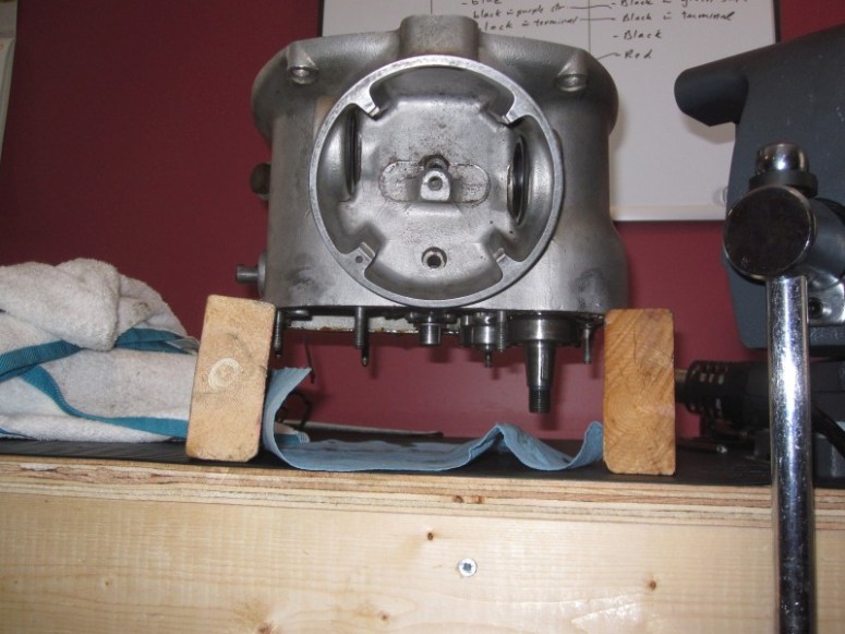
This is my first attempt at removing the output shaft, and it was unsuccessful. I tried heating up the front of the transmission and tapping it hoping the shaft would fall off, but it didn’t. The day’s work was done, so called it quits, but I think the plan will be to freeze the transmission, to shrink all the parts, then quickly heat up the front of it with a torch to expand the pocket that holds the bearings in place. Yeah, that should work.
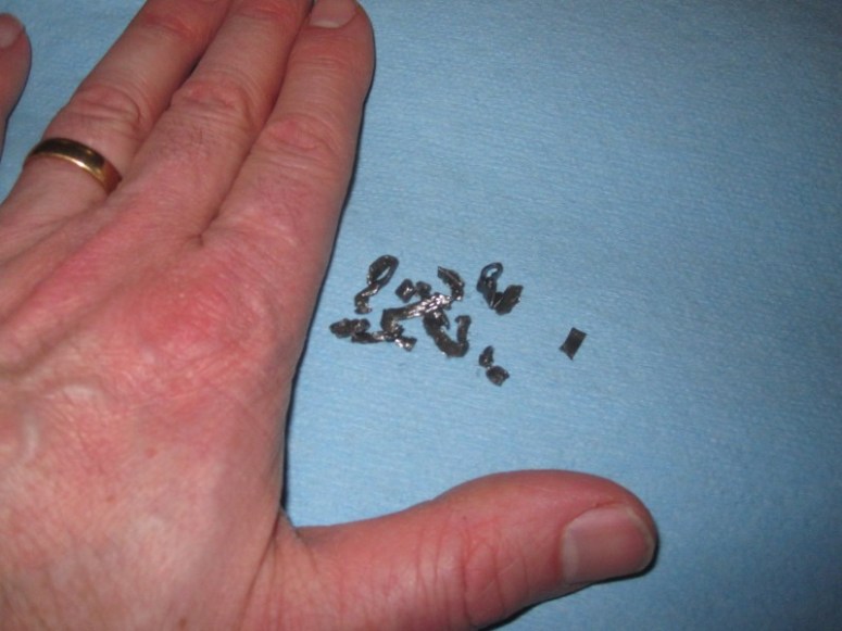
This is stuff I found in the transmission case, with my hand for perspective. Looks like a complete bearing cage to me. Really need to find the unhappy bearing, would not want to go anywhere with this transmission in this state.
21 February 2017
for a “Take two” on the gearbox, I put in the “Canadian Freezer” AKA outdoors overnight to chill it down to -16.
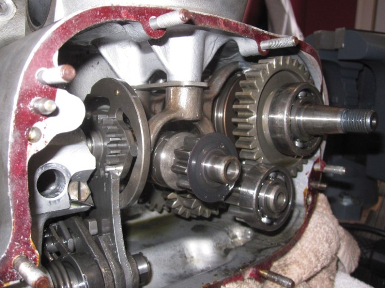
The next step was to bring it in, placed upside down on the bench and I heated up the front part of the case with a propane torch, to the point of spit sizzling on the case. As these shaft bearings are inference fits onto the recessed areas of the case, the aluminium heated up and dilated quicker than the bearings. With a bit of tugging and some sharp raps on the case with a plastic hammer, the shafts came out.
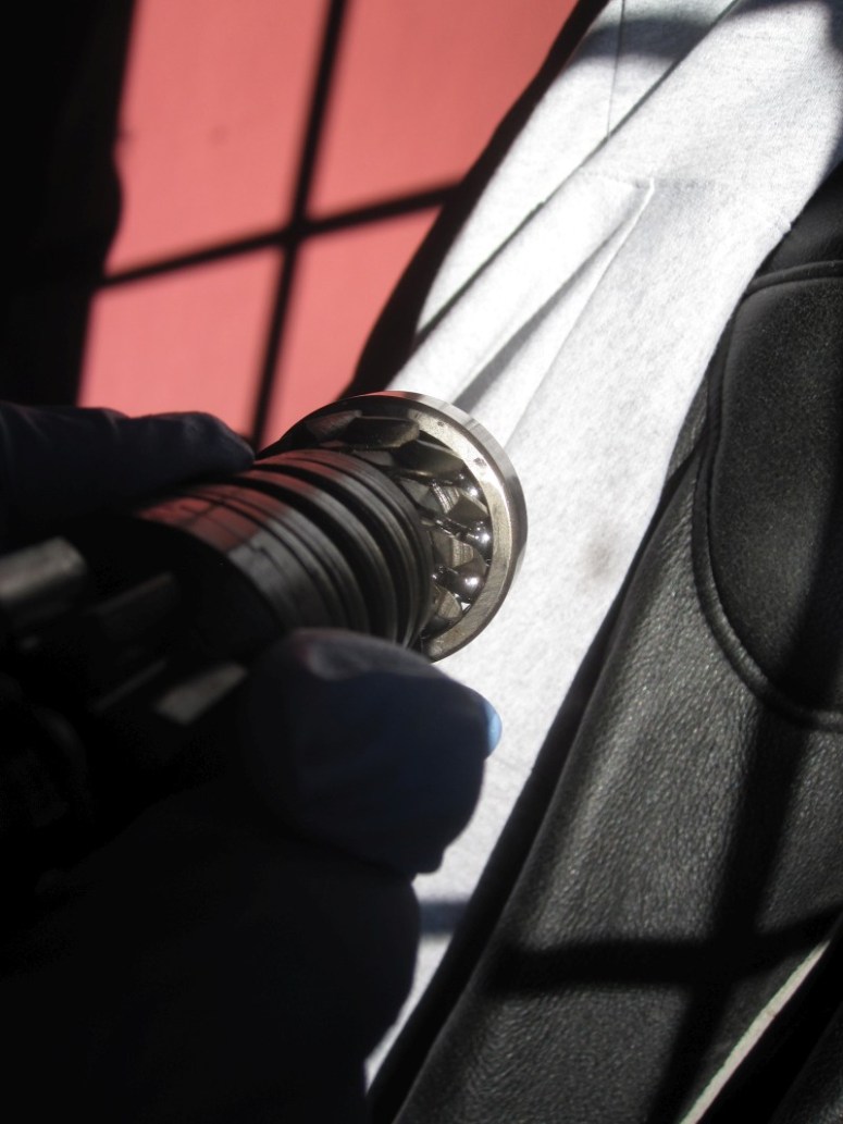
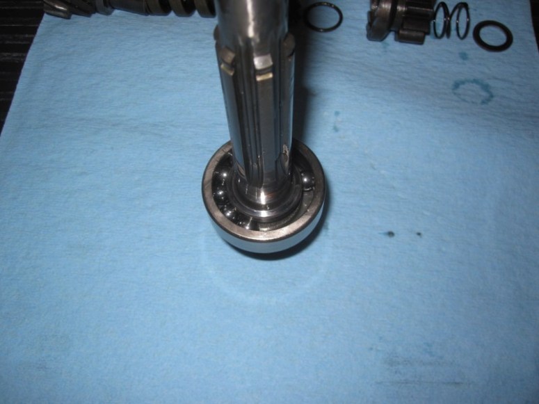
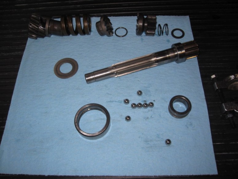
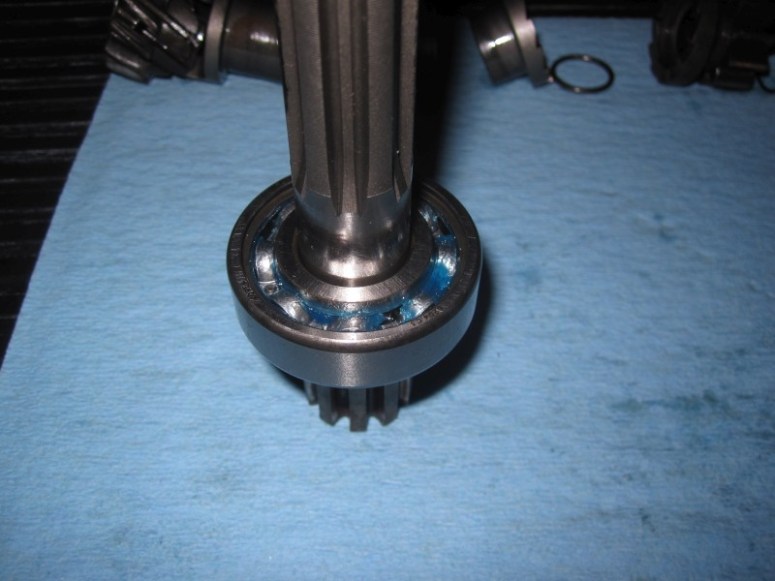
As speculated, the bad boy was the input shaft forward bearing. In the image below we can see some balls grouped together, without a hint of a cage to be seen. Balls touching. Not good.
The next steps will be disassembling the input shaft to remove the bad bearing, but that’s all the time I have for today.
24 February 2017
Took the time today to disassemble the input shaft, in hopes of replacing the bearing. First step was to pry off the little washer, which allowed the spring and the kickstarter gear to slide off.
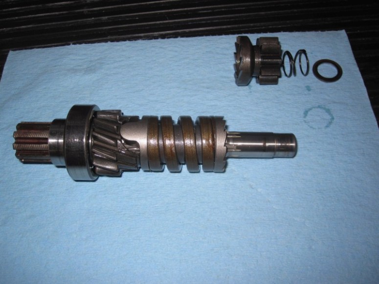
The next step was to compress the spring to gain access to the circlip that holds the gears in place. This was accomplished with the help of a vice and a box-end wrench to have room to remove the circlip.
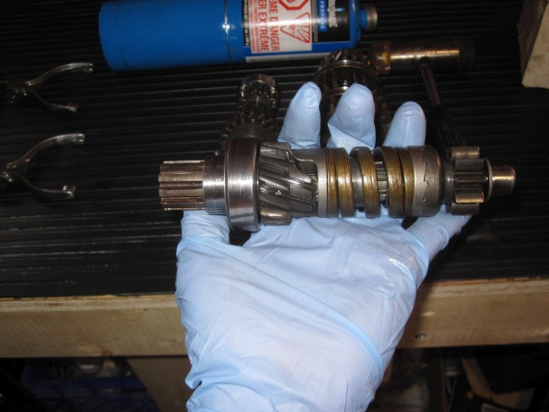
Here we see the shaft disassembled down to the faulty bearing.
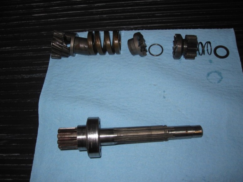
There should be a bearing cage in there.
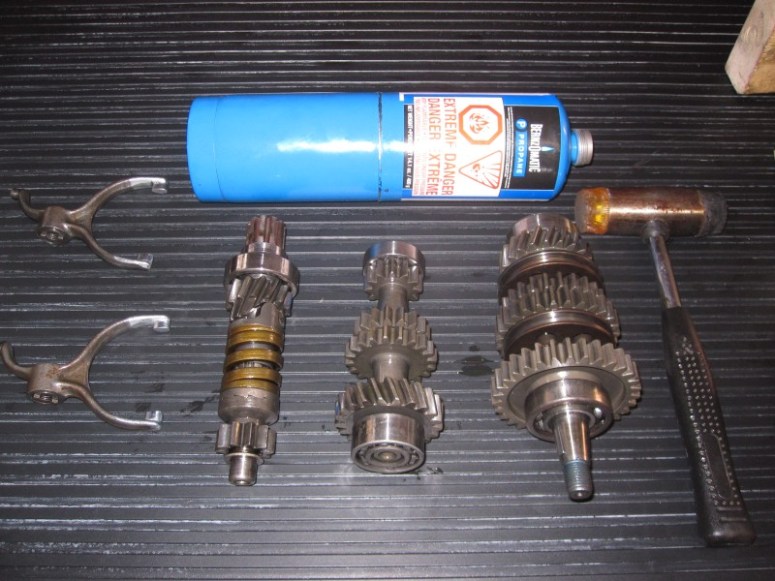
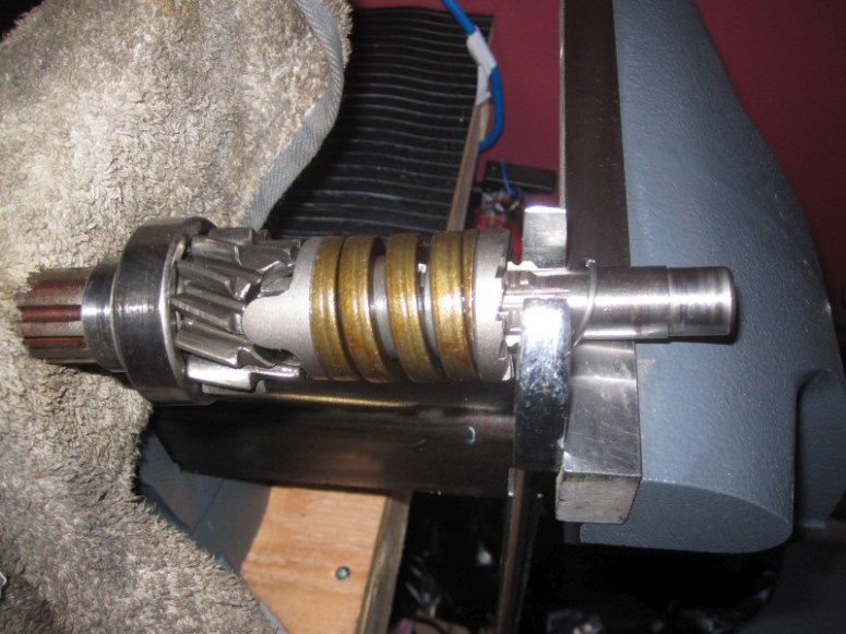
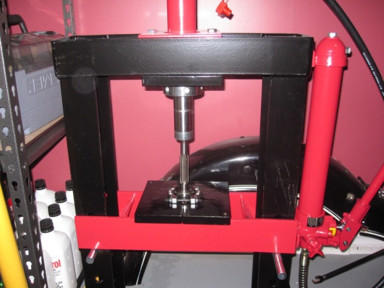
To remove the bearing from the shaft, a bearing seperator (splitter) was used
which allowed me to press out the shaft from the bearing.
Here we have the bad bearing removed
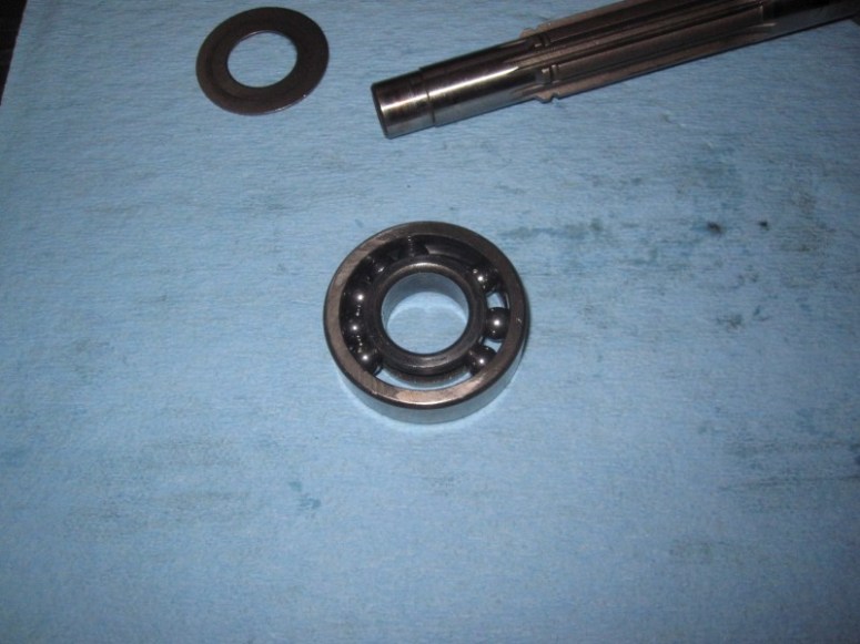
I still can’t believe how lucky we were that this didn’t decide to grenade while out for a ride. There was nothing holding the balls in place.
As easy as the old bearing came off, the new one was pressed on. The rest was simply reversal of the procedure to put everything back together again.
March 19 2017
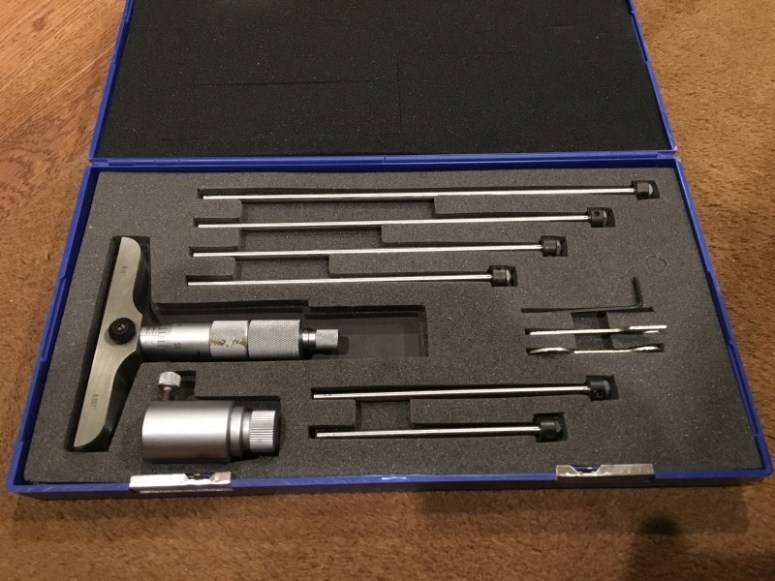
The part of this that I was apprehending was upon me. From my reading the reassembly of the transmission is a very finicky procedure, requiring precise measurements and proper shimming of the shafts so they fit just so in the case. At first I thought that since I’ve only replaced one bearing, then the shimming should stay pretty much unchanged except for the input shaft. I was wrong. This was another one of those moments where I realized that I was lacking some form of specialized tool, so I ordered and received this, a depth micrometer.
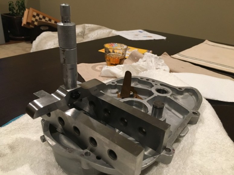
This, along with some steel parallels let me measure precisely how deep the recesses for the rear bearings are within the transmission housing cover.
Then, along with yet another specialize plate I was able to measure exactly how much the bearings protrude from the case.
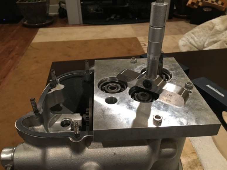
Take one number, substract the other, then allow 0.0039 inches for play, then you have the measurement for the required shims to be installed on each shaft. This was significantly different than what was in the box when I took it apart.
Shims in place, some purple gear oil splashed around the gears, and it’s ready to get the lid back on.
The kickstarter gear was held in proper position with a vice grip on the kickstarter shaft tie-wrapped to the housing. This allowed me to use both hands to put the cover back on.

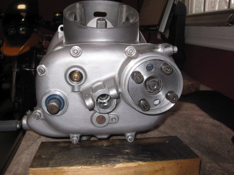
Finished product. Of course once everything was buttoned up again, I tested the neutral indicator switch and it was always on. The tab had shifted a bit when I put the cover back on so I had to basically take everything apart again. Was so nice I did it twice !
Here’s a pic of the finished rear.
Some moly paste for the input splines, the clutch pushrod inserted along with the little felt ring,
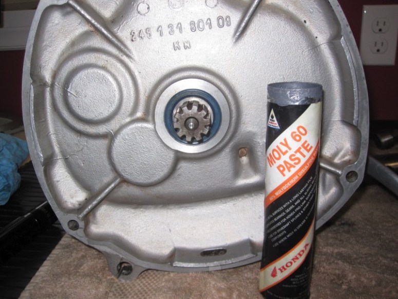
… and the transmission is ready to go back in.
